For some time now there has been a lot of interest in pager-motor powered micro planes. There is also a lot of confusion about how to best put these motors to use and what the differences between motors are. In this article I take a look at many of the commonly available 6mm pager and Bit Car motors. I also examine the Didel 4.5 ohm pager in some detail as well as gears, props, and gearboxes for pager motors.
 As
usual several friends provided useful technical help and advice as I proceeded
with the tests for this article. Roger Carignan did parallel tests of the
4.5 ohm Didel pager when we first got it and were trying to figure out
exactly what it was capable of. He and Matt Keennon were also very useful
sounding boards for preliminary results and sources of advice. Carl Martin
made gearboxes that allowed motors to be easily swapped and thus many different
motors to be tested. He also made gearboxes that allowed testing pager
motors at seven different gear ratios. Hopefully the result of all this
is to bring some clarity to the confusion surrounding pager and Bit Car
motors.
As
usual several friends provided useful technical help and advice as I proceeded
with the tests for this article. Roger Carignan did parallel tests of the
4.5 ohm Didel pager when we first got it and were trying to figure out
exactly what it was capable of. He and Matt Keennon were also very useful
sounding boards for preliminary results and sources of advice. Carl Martin
made gearboxes that allowed motors to be easily swapped and thus many different
motors to be tested. He also made gearboxes that allowed testing pager
motors at seven different gear ratios. Hopefully the result of all this
is to bring some clarity to the confusion surrounding pager and Bit Car
motors.
6mm Motor Overview
Pager motors are a class of inexpensive motors originally used to power a vibrating alert in pagers and cell phones. They are often coreless, but can also use traditional cored technology. One question we might have about a particular motor is how to determine exactly which motor it is. The easiest way is to measure the resistance in ohms across the two terminals or leads. To measure the resistance first connect the motor leads to a multimeter. Put a pinion on the motor shaft and then insert it into a short balsa stick with a hole in the middle that can be pressed over the pinion. The stick makes it easier to precisely position the motor shaft. Measure the resistance, then rotate the shaft slightly and measure again. Repeat this several times. The motor shaft must be completely at rest each time or the reading will not be valid. Use the highest measure because lower readings may occur if the motor shaft is positioned such that the brushes are straddling the commutator for two sets of windings rather than one. Finally, the resistance readings can differ by as much as +/- 1 ohms for identical motors from the same source. With the resistance of the motor in hand and pictures of the motors in this article or knowing the motor's source you should be able to determine approximately which motor you have and how to use it.
Not all pager or Bit Car motors are created equal. There are a number of different manufacturers making Bit Car motors. It is not feasible to attempt to catalog them all here. Motors from cars purchased at the same time may last for the same amount of time or perform differently. And, motors from different manufacturers may not perform or last the same. The Bit Car manufacturers may source their motors from more than one manufacturer or switch from time to time. Thus it's difficult to know for certain exactly what you are getting. The Didel motors are to some extent the exception as they come from one motor manufacturer which does not change. However, even within Didel motors there can be some moderate variation just due to the manufacturing process. Remember, these motors cost only a few dollars at retail and are being cranked out in volume in Asia. Some variation is bound to occur in this high-volume low-cost manufacturing process.
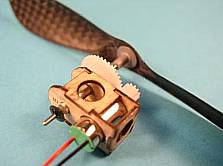
Connection methods fall into three main categories. Pager motors generally come with wire leads exiting the back bell, but occasionally on the side near the front bell. Bit Car motors generally make their ground connection through the motor case and their positive connection through a small terminal on one side of the back bell, or through a diamond shaped connection in the center of the back bell. This makes it more difficult to solder up the Bit Car motors. The Didel pager motors with resistances less than 10 ohms are essentially Bit Car motors with wire terminals exiting the back bell. This makes them easier to use.
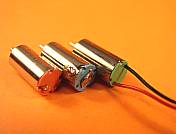 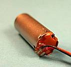 |
| Connection methods left to right: side-bell contact, center-bell contact, wire connections. The picture on the right shows the distinctive connections for the surplus 6.1mm brown bell pager. |